Electrical Engineering ⇒ Topic : Electromagnetic Torque
|
|
| Maninder
| |
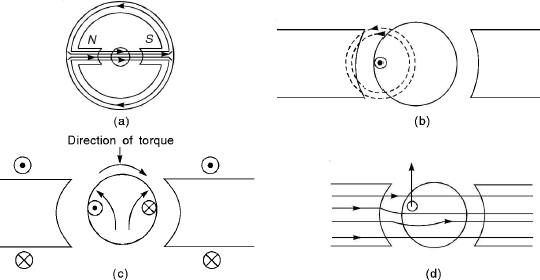
In Figures (a) and (b)
Electromagnetic torque. the flux distribution has been shown due to the north and south poles of the stator and there is no current through armature conductors. In this case, there is no flow of current through the armature. The flux distribution due to the flow of current through the armature conductor is shown in Figure (c) and there is no flow of current through the field coils in stator. The combined distribution of flux has been shown in Figure (d) when there is flow of current through the field coils and armature conductors. There is one current carrying coil in armature as shown in Figure (c) which carries current in upward direction. It has been indicated by dot under stator north pole and by cross under south pole. Here rotor current produces rotor flux and this creates two poles on the rotor. The stator N pole repels rotor N pole and stator S pole attracts rotor N pole. Similarly, stator S pole repels rotor S pole and stator N pole attracts rotor S pole. It is clear that a clockwise torque is produced. This torque is called interaction torque or electromagnetic torque. If the field is kept fixed, i.e., the direction of field current remains same and if the armature conductors under N-pole and S-pole carry current in upward and downward direction respectively, the torque will be anticlockwise. Similarly, if the poles N and S are interchanged and the direction of the current through the armature conductors remain same, again anticlockwise torque is produced. If the direction of both are changed, clockwise torque will be produced. | |
|
| |
!! OOPS Login [Click here] is required for more results / answer