Electrical Engineering ⇒ Topic : Induction Wattmeters , construction and its working
|
|
| David
| |
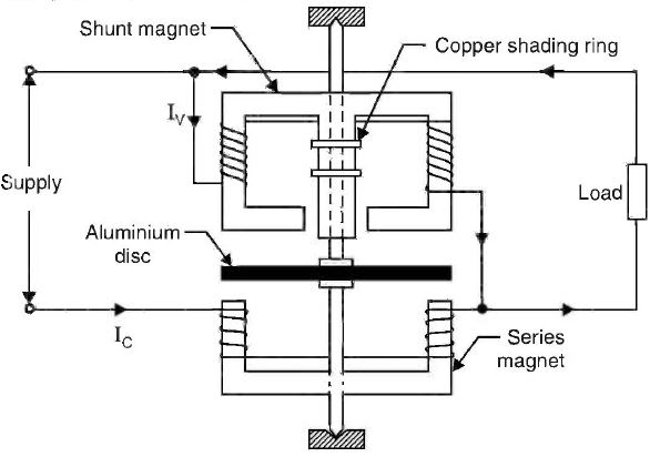
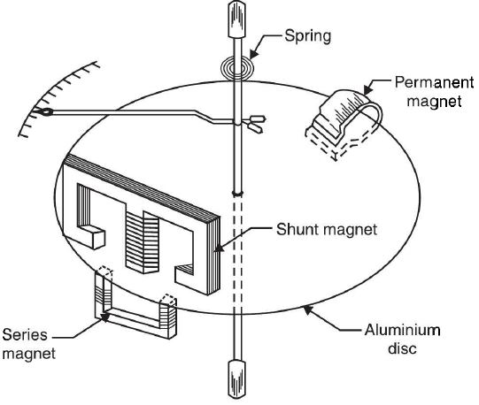
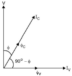
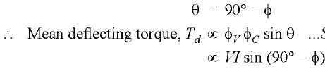
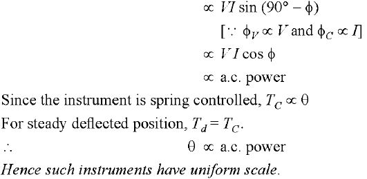
Induction Wattmeters The induction type wattmeter can be used to measure a.c. power only in contrast to dynamometer wattmeter which can be used to measure d.c. as well as a.c. power. The principle of operation of an induction wattmeter is the same as that of induction ammeter and voltmeter i.e., induction principle. However, it differs from induction ammeter or voltmeter in so far that two separate coils are used to produce the rotating magnetic field in place of one coil with phase split arrangement,Fig. (b) shows the physical arrangement of the various parts of an induction wattmeter. Construction. Fig (a) shows the principal parts of an induction wattmeter. (i) It consists of two laminated electromagnets. One electromagnet, called shunt magnet is connected across the supply and carries current proportional to the supply voltage. The coil of this magnet is made highly inductive so that the current (and hence the flux produced) in it lags behind the supply voltage by 900. The other electromagnet, called series magnet is connected in series with the supply and carries the load current. The coil of this magnet is made highly non-inductive so that angle of lag or lead is wholly determined by the load. (ii) A thin aluminium disc mounted on the spindle is placed between the two magnets so that it cuts the flux of both the magnets. The controlling torque is provided by spiral springs. The damping is electro-magnetic and is usually provided by a permanent magnet embracing the aluminium disc See Fig. (b). Two or more closed copper rings (called shading rings) are provided on the central limb of the shunt magnet. By adjusting the position of these rings, the shunt magnet flux can be made to lag behind the supply voltage by exactly 900 figure (a) figure (b) Working. When the wattmeter is connected in the circuit See Fig. (a) to measure a.c. power, the shunt magnet carries current proportional to the supply voltage and the series magnet carries the load current. The two fluxes produced by the magnets induce eddy currents in the aluminium disc.The interaction between the fluxes and eddy currents produces the deflecting torque on the disc,causing the pointer connected to the moving system to move over the scale. The pointer comes to rest at a position where deflecting torque is equal to the controlling torque. Let V = supply voltage Iv = current carried by shunt magnet lc = current carried by series magnet (= load curent I) cos Φ = lagging power factor of the load The phasor diagram is shown in Fig. (c). The current Iv in the shunt magnet lags the supply voltage V by 90° and so does the flux Φv produced by it. The current lc in the series magnet is the load current and hence lags behind the supply voltage V by Φ. The flux ΦC produced by this current (i.e., Ic) is in phase with it. It is clear that phase angle θ between the two fluxes is 90° - Φ) i.e., figure (c)
| |
|
| |
!! OOPS Login [Click here] is required for more results / answer