Electrical Engineering ⇒ Topic : Cathode Ray Tube
|
|
| Gopal
| |
One of the most useful and important components of the CRO is the cathode ray tube (CRT). It is the heart of the oscilloscope and converts the electrical signal into a visual signal. In an oscilloscope, electrons are emitted from a cathode, are then accelerated to a very high speed and are finally brought to focus on a fluorescent screen where it is made visible. By deflecting the electron beam over the fluorescent screen in response to the input electrical signal, by using a suitable deflecting arrangement, is exact shape can be obtained on the screen. The oscilloscope uses the electron beam to do the remarkable jobs that it does, by transforming the electrical signals into visual ones. Since the electrons have negligible mass, they respond almost instantaneously to the variations in the input electrical signals and hence an oscillo-scope can give a fast visual reproduction of the electrical signals fed into it. Figure shows the various components of a cathode ray tube. It consists of a cathode (C), a grid (G), two anode discs (A1 and A2), a focussing electrode (F) and the vertical and horizontal deflecting plates (X and Y) as shown in the figure. The cathode is the indirectly heated type and emits electrons. These electrons are accelerated by a cylindrical anode (F) which has a hole at its centre through which the electron beam passes. FIGURE A cathode ray tube (CRT) The intensity of the electron beam is controlled by the grid. Thus, by varying the grid potential the brilliance of the spot on the fluorescent screen (S) is controlled. The anode discs A1 and A2 are usually connected together and are maintained at a high positive potential (10 kV to 15 kV) with respect to the cathode, thus the electrons passing through the grid G are accelerated to very high velocities. The electron beam shoots through the small apertures in A1 and A2 and their impact on the fluorescent screen produces a luminous patch on the screen. This patch can be focussed into a bright spot by varying the potential of the focussing electrode, F. The combination of A1 and A2 and F is called the electron lens and the system of electrodes C and G that produce and control the electron beam is called the electron gun. The electron gun assembly provides a narrow accelerated beam of electrons to be focussed on to the screen (S). The entire cathode ray tube assembly is kept inside a glass envelope, which is of conical shape and evacuated to a very high vacuum. The inner walls of the glass envelope between the neck and the screen is usually coated with a conducting material called aquadag. This conducting surface prevents the walls of the glass envelope from getting charged to high negative voltages.Beyond the accelerating anode A2 (see Figure), the electron beam is moving rapidly and has well defined energy. This beam passes between a pairof flap plates called the vertical deflecting plates (Y). If a potential is applied across these plates, an electric field is created between them and it will cause a movement of the beam, either up or down, vertically on the screen. Next the electron beam will pass through another pair of plates called the horizontal plates (X). When a potential is applied across these plates, the resultant field will help to move the beam either to the right or the left, horizontally on the screen. The beam of electrons strikes the screen. The screen (S) is the inside face of the glass envelope and is coated with some fluorescent material, such as, zinc oxide or zinc orthosilicate. When the electron beam with a very high velocity strikes the screen, a spot of light is produced at the point of impact | |
|
| |
| Lalan
| |
Cathode Ray Tube Cathode ray tubes are classified in many ways as follows:
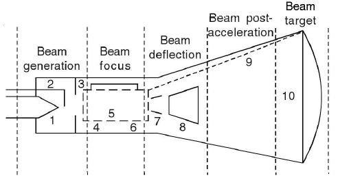
The cathode ray tube may be divided into five sections: (i) beam generation, (ii) beam focussing, (iii) beam deflection, (iv) beam post-acceleration, and (v) beam target or screen. Figure (a) shows the cathode ray tube consisting of the following parts: (i) filament heating, (ii) indirect cathode, (iii) grid, (iv) pre-accelerating anode, (v) focussing anode, (vi) accelerating anode, (vii) vertical deflection plate, (viii) horizontal deflection plate, (ix) aquadag coating, and (x) fluorescent screen. figure (a) Cathode ray tube Electrons are emitted by the cathode by the process of thermionic emission. The grid being negative, repels the electrons and they stream out of the pinhole in the grid towards the pre-acceleration anode which is held positive. There is a similar pinhole in the pre-acceleration anode from which narrow beam emerges. The beam acquires sufficient acceleration on account of the anode and cathode potential difference. The grid voltage is controlled by the 'Brightness or Intensity' knob on the CRO | |
|
| |

!! OOPS Login [Click here] is required for more results / answer