Electrical Engineering ⇒ Topic : Moving-Iron Frequency Meter
|
|
| Daniel
| |
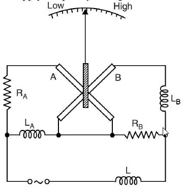
Moving-Iron Frequency Meter This meter is also known as Weston frequency meter and operates on the principle of variation of impedance of a circuit with the change in supply frequency. Principle. The action of this meter depends upon variation of current distribution in two parallel circuits one inductive and the other non-inductive -- Construction. Fig. (a) shows the constructional details of a moving-iron frequency meter. It consists of two coils A and B mounted perpendicular to each other.The coil A has a resistor RA in series while coil B has an inductance LB in series. Circuit A is in parallel with inductance LA while B is in parallel with resistance RB. At the centres of the coils is pivoted a long and thin soft-iron needle which carries the pointer. No controlling torque is required; damping being provided by air friction. The series inductance L helps to suppress higher harmonics in the current waveform and therefore tends to minimise the waveform errors in the indications of the instrument.The currents flowing through coils A and B produce opposing torques. The circuit parameters (i.e., RA, LA, RB and LB) are so designed that at normal frequency of supply, the currents in the two coils are equal and the pointer is at the centre of the scale. figure (a) Working. When the meter is connected to the supply whose frequency is to be determined, the currents flowing through coils A and B set up magnetic fields. The magnitude of magnetic fields will depend upon the amount of current flowing through the coils. The moving system would tend to align itself along the resultant magnetic field of two coil :
| |
|
| |
!! OOPS Login [Click here] is required for more results / answer