Electrical Engineering ⇒ Topic : Speed Control of Induction Motor
|
|
| Kunal
| |
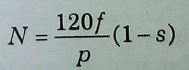
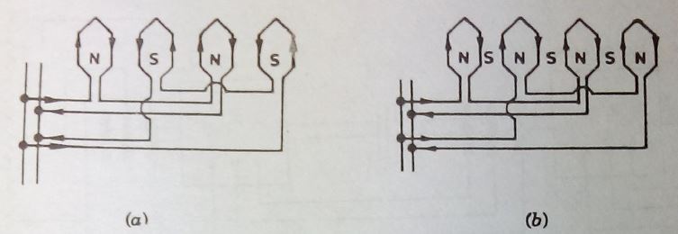
SPEED CONTROL OF INDUCTION MOTORS The rotor speed of an induction motor may be stated by the equation where, N = rotor speed in r.p.m. f = frequency of supply, p = number of poles, and s = fractional slip. This shows that a change in any one of these quantities will affect its speed, namely : (i) change of frequency; (ii) change of number of pòles and (iii) change of slip. Control by Changing Frequency:- This method is impractical for most applications because frequency of the supply must remain fixed. In special cases where the motor load is the only load connected to generators, the speed of the prime-movers may be varied to change the supply frequency and thus change the motor speed. The range over which the speed may be varied in this way, however, is limited by the range of economical speeds of the drives. This method of control has been applied to a limited extent in ship propulsion. Control by Changing Number of Poles:-Change in the number of poles is effected by making change in the stator winding connections with the help of suitable switching arrangement. When the speed ratio is 2: 1, the 'Consequent Pole' method is adopted and is shown diagrammatically in Fig (1). Fig.(1) Speed control by changing number of poles Two distinct windings are on the stator producing the same number of poles, one winding creates two N-poles and the other two S-poles as shown in Fig. 1(a). This gives four poles,and the synchronous speed at 50-Hz is 1500 r.p.m.If the connection of one 6f the windings is reversed [Fig. 1(b)], there will be in all four N-poles or four S-poles, depending upon which of the winding connection is reversed. But in between these poles other four poles of opposite polarity will be created. Thus the stator now has eight poles and its synchronous speed is 750 r.p.m. The 2 : 1 change in speed is rather drastic. Hence motors are manufactured with two windings one is so wound that is created 8-poles and the other 10-poles, the synchronous speeds being 750 r.p.m. and 600 r.p.m. respectively. But the disadvantage is that at either speed only 50 per cent stator copper is utilised, since only one winding is in use at a time. In the case of squirrel-cage motors, change in the number of poles on the stator does not affect the existing arrangement on the rotor. But in case of wound rotors, the number of poles on the stator must equal to the number of poles on the rotor. Otherwise there will be a greater reduction in torque due to some rotor conductors developing a negative torque. 3. Control by Changing Slip. Change in slip is effected by introducing an external resistance in rotor circuit of wound rotors. But this is done at the sacrifice of efficiency and besides the speed regulation is poor. These disadvantages are more or less overcome by :
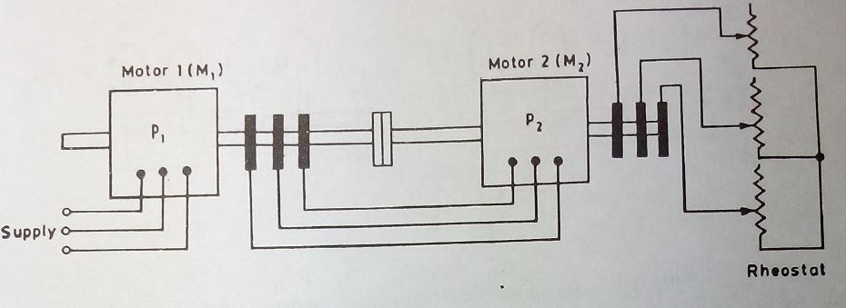
4. Control by Cascade or Tandem Connection. Where multiple speeds are desired,motors are sometimes operated in tandem or cascade. When so used, two motors are rigidly coupled to the same shaft or are otherwise mechanically linked, as by means of gears. The stator winding of the first is connected to the mains in the usual way, while that of the second stator is fed from the rotor winding of the first, as shown in Fig.(a) Fig.(a)Wound rotor motors connected in tandem If the two machines are designed for the same voltage, as is usually the case, the turn ratio of stator to rotor of the first machine should be unity. The second rotor may have a cage winding or a polyphase winding like its stator. In the latter case the rotor circuit of the second motor is connected to slip rings in the usual way, in order that resistance may be introduced while starting and for securing additional speed control when running.The motors maybe so connected that both tend to run in the same direction, or the phase rotation of cne motor may be reversed, thus tending to make it rotate in the reverse direction.In either case the set will run after it is started, but in the latter case no starting torque is developed, and for this reason this connection is little used. If the first machine has p1 poles and the second has p2 poles, the synchronous speed of the set is that of a motor with p1 + p2 poles for the first case and p- p2poles for the second. If p1 and p2 are not equal, four synchrono'us speeds are possible, two with tandem operation and one for each motor separately. Some applications of this method of control are found in European railways. | |
|
| |
| Sunita
| |
SPEED CONTROL OF INDUCTION MOTOR The speed of an induction motor can be controlled by changing the number of poles (where P is even number) and by changing frequency f By changing frequency only, it is not possible to control the speed. In this case, V/f ratio should be kept constant | |
|
| |
!! OOPS Login [Click here] is required for more results / answer