Electrical Engineering ⇒ Topic : Bandwidth of Parallel Resonant Circuit
|
|
| Seema
| |
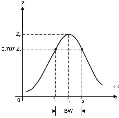
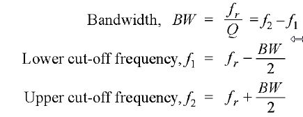
Bandwidth of Parallel Resonant Circuit Just as the bandwidth of a series resonant circuit is defined from current-frequency curve, similarly the bandwidth of a parallel resonant circuit is defined from impedance-frequency curve as shown in Fig.(a) The bandwidth of a parallel resonant circuit is defined as the range of frequencies over which the circuit impedance is equal to or greater than 70.7% of maximum circuit impedance (i.e. Zr, the impedance at resonance). The circuit impedance is maximum (i.e. Zr) at fr while half-power points (i.e. f1 and f2) occur at 0.707 Zr. Using the same procedure as was used for series resonant circuit, it can be shown that figure (a)
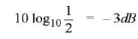
The points on the curve in Fig. (a) where the upper and lower cut-off frequencies intersect the curve (at 70.7% of Zr) are called the half-power points. Thus the bandwidth (BW) of a parallel resonant circuit is often refen-ed to as the band of frequencies between the half-points on the impedance-frequency curve. At half-power frequencies (i.e. f1 and f2), the power dissipated in the circuit is one-half of that dissipated at resonant frequency (J,). A signal at a frequency outside the bandwidth is transmitted with less than 1/2 the output power of a signal of similar strength at the resonant frequency. Note. The power at cut off frequencies is half that at the resonant frequency and are known as half power frequencies. They are also called -3 dB frequencies because power decreases by 1/2 and in decibels it is | |
|
| |
| Seema
| |
Bandwidth of Parallel Resonant Circuit Just as the bandwidth of a series resonant circuit is defined from current-frequency curve, similarly the bandwidth of a parallel resonant circuit is defined from impedance-frequency curve as shown in Fig.(a) The bandwidth of a parallel resonant circuit is defined as the range of frequencies over which the circuit impedance is equal to or greater than 70.7% of maximum circuit impedance (i.e. Zr, the impedance at resonance). The circuit impedance is maximum (i.e. Zr) at fr while half-power points (i.e. f1 and f2) occur at 0.707 Zr. Using the same procedure as was used for series resonant circuit, it can be shown that figure (a)
The points on the curve in Fig. (a) where the upper and lower cut-off frequencies intersect the curve (at 70.7% of Zr) are called the half-power points. Thus the bandwidth (BW) of a parallel resonant circuit is often refen-ed to as the band of frequencies between the half-points on the impedance-frequency curve. At half-power frequencies (i.e. f1 and f2), the power dissipated in the circuit is one-half of that dissipated at resonant frequency (J,). A signal at a frequency outside the bandwidth is transmitted with less than 1/2 the output power of a signal of similar strength at the resonant frequency. Note. The power at cut off frequencies is half that at the resonant frequency and are known as half power frequencies. They are also called -3 dB frequencies because power decreases by 1/2 and in decibels it is | |
|
| |
!! OOPS Login [Click here] is required for more results / answer