Electrical Engineering ⇒ Topic : Thevenins Theorem
|
|
| David
| |
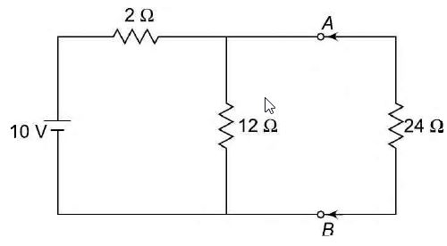
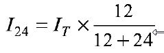
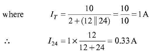
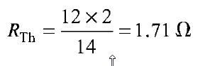
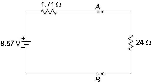
Thevenin's Theorem In many practical applications, it is always not necessary to analyse the complete circuit; it requires that the voltage, current, or power in only one resistance of a circuit be found. The use of this theorem provides a simple, equivalent circuit which can be substituted for the original network. Thevenin's theorem states that any two terminal linear network having a number of voltage current sources and resistances can be replaced by a simple equivalent circuit consisting of a single voltage source in series with a resistance, where the value of the voltage source is equal to the open circuit voltage across the two terminals of the network, and resistance is equal to the equivalent resistance measured between the terminals with all the energy sources are replaced by their internal resistances.According to Thevenin's theorem, an equivalent circuit can be found to be replace the circuit in Fig. (a). In the circuit, if the load resistance 24 Ω, is connected to Thevenin's equivalent circuit, it will have the same current through it and the same voltage across its terminals as it experienced in the original circuit. To verify this, let us find the current passing through the 24 Ω, resistance due to the original circuit. figure (a)
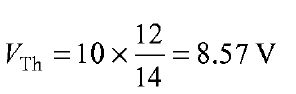
The voltage across the 24 ΩSI resistor = 0.33 X 24 = 7.92 V. Now let us find Thevenin's equivalent circuit. The Thevenin voltage is equal to the open circuit voltage across the terminals 'AB', i.e. the voltage across the 12Ω resistor. When the load resistance is disconnected from the circuit, the Thevenin voltage. The resistance into the open circuit terminals is equal to the Thevenin resistance figure (b) Thevenin's equivalent circuit is shown in Fig. (b). Now let us find the current passing through the 24 Ω resistance and voltage across it due to Thevenin's equivalent circuit. The voltage across the 24 Ω resistance is equal to 7.92 V. Thus, it is proved that RL( = 24 Ω) has the same values of current and voltage in both the original circuit and Thevenin's equivalent circuit. | |
|
| |
| Samual
| |
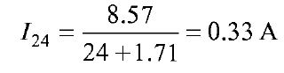
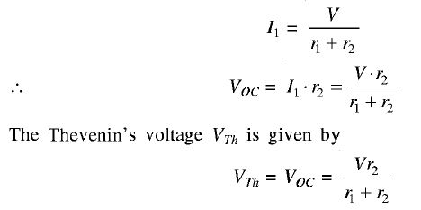
THEVENIN'S THEOREM This theorem is also extensively used in networks to determine the current through any element or voltage across any element in a network without rigorous calculation for solving a set of network equations. This theorem states that Any linear active bilateral network can be replaced by an equivalent circuit consisting of a voltage source in series with a resistance. The voltage source is open circuit voltage across the open circuited load terminals and the resistance being the internal resistance of the source network looking from the open circuited load terminals. Explanation Let us consider a simple circuit shown in Figure 1 (a). The current through rL will be found out by Thevenin's theorem. figure (1) First of all remove the element rL from the circuit shown in Figure 1 (a). The circuit configuration is illustrated in Figure 1 (b). Now, let us apply the following procedure: (i) Here Voc is the voltage across resistance r2 since there is no current through r3. The current through r2 is given by [from Figure 1 (b)]
(ii) Next we will find the Thevenin's resistance RTh. The voltage source is deactivated by a short circuit as the source does not have any internal resistance. The circuit is shown in Figure 1 (c). (iii) After that we will reconnect the load resistance II across the terminals A-B. The circuit is shown in Figure 1(d). Therefore, the current I through rL is given by | |
|
| |
| Mason
| |
Thevenin's theorem for an a.c. circuit is the same as that for a d.c. circuit except that phase angle of all quantities (impedances, voltages and cun-ents) must be taken into consideration.Therefore, Thevenin's theorem for a.c. circuits can be stated as under : Any two-terminal linear a.c. circuit can be replaced by a single a.c. voltage source (VTh) in series with a single impedance (ZTh) The procedure for finding
FIGURE i & ii Figure (ii) shows the Thevenin equivalent circuit of the a.c. circuit shown in Figure (i). Note that behind terminals AB, the a.c. circuit is replaced by a single a.c. voltage source | |
|
| |
| William
| |
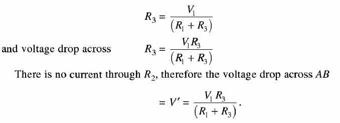
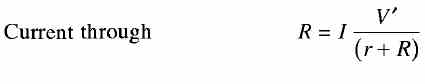
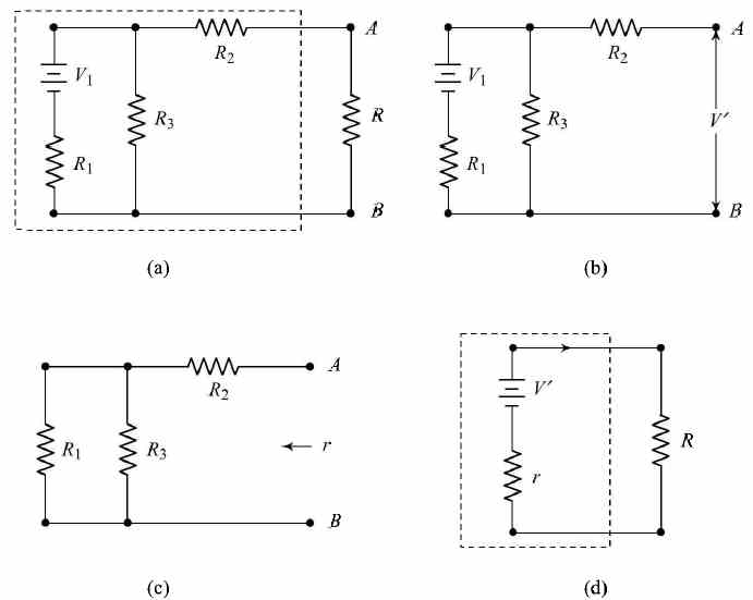
Thevenin's Thevenin's Theorem is Stated as Follows "The current through a load resistor R connected across any two points A and B of an active network (containing resistors and one or more sources of emf is obtained by dividing the potential difference between A and B, with R disconnected by (R+ r), where r is the resistance of the network measured between points A and B with R disconnected and sources of emf replaced by their internal resistances." Consider a network shown in Fig. 1 (a). A and B are the two points of the network which consist of resistors having resistances of R2 and R3 and a voltage source of emf V and internal resistance R1. The current through the load resistance R connected across AB has to be calculated. Suppose the load resistance R is disconnected as shown in Fig. 1 (b). Then current through
The network with load disconnected and the voltage source V replaced by its internal resistance R1 is shown in Fig. 3.23(c). Now, the resistance of the network between A and B = r = R2 + (R1R3lR1 + R3). As per the definition of Thevenin's theorem, the active network enclosed by the dotted line in Fig. 1 (a) can be replaced by a simple circuit as shown by the dotted line in Fig. 1 (d), consisting of a source having an emf equal to V' (the open circuit potential difference between A and B) and an internal resistance r given by the following relationship
FIGURE (1) A circuit to illustrate Thevenin's theorem | |
|
| |
 ............ (1)
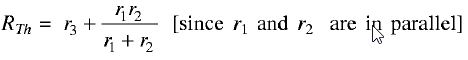 .......... (2)
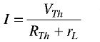 .............. (3)
 and
and  is the same as for d.c. circuits i.e.
 is the open circuit voltage at the considered terminals (say terminals AB) and the series impedance
  is the impedance at terminals AB with all sources replaced by their internal impedances.

 in series with a single impedance
  .
.
!! OOPS Login [Click here] is required for more results / answer