Electrical Engineering ⇒ Topic : Moving-Iron Power Factor Meter
|
|
| Daniel
| |
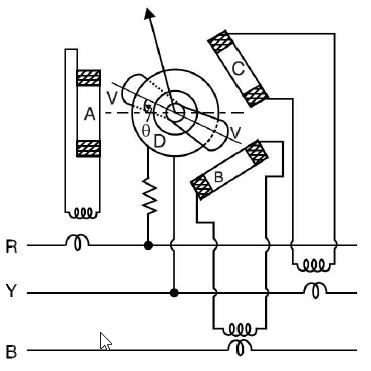
Moving-Iron Power Factor Meter Several types of moving-iron power factor meters are available. The arrangement shown in Fig. (a) is of rotating field type and is suitable for the measurement of pf. of balanced 3-phase circuits. The mechanism consists of : figure (a)
Working. The moving iron system is placed inside the fixed coil D so that the moving iron carries an alternating flux. This alternating flux interacts with the fluxes produced by the three coils. The total torque on the moving system is equal to the sum of the torques due to currents in the coils A, B and C. The pointer will come to rest at a position where total torque is equal to zero. By constructing the phasor diagram and using the rules of trigonometry, it can be proved that for steady deflection of the pointer, θ = Φ ,the load p.f. angle Thus deflection (θ ) of the pointer from the reference axis is equal to phase angle (Φ) between each current and the corresponding phase voltage. The meter is scaled to read power factor (cos Φ) directly.the load p.f. angle | |
|
| |
!! OOPS Login [Click here] is required for more results / answer