Electrical Engineering ⇒ Topic : Delta connected system
|
|
| Daniel
| |
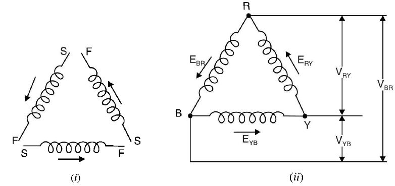
Delta (Δ) or Mesh Connected System In this method of interconnection, the dissimilar ends of the three phase windings of the alternator are joined together i.e., finishing end of one phase is connected to the starting end of the other phase and so on to obtain mesh or delta as shown in Fig. (a). The three line conductors are taken from the three junctions of the mesh or delta and are designated as R, Y and B. This is called 3-phase, 3-wire, delta connected system. The arrangement is referred to as mesh connection because it forms a closed circuit. It is also known as delta connection because the diagram has the appearance of Greek letter delta (Δ). In delta connection, no neutral exists and, therefore, only 3-phase, 3-wire system can be formed. figure (a) The following points may be noted : (1) As can be seen from Fig. a (ii), only one phase is included between any two lines. Hence magnitude of voltage between any two lines (i.e. line voltage) is equal to the magnitude of phase voltage i.e. Line voltage magnitude, VL = Phase voltage magnitude (Eph) The three phase voltages (= line voltages) are equal in magnitude but displaced 120° from one another (2) When 3-phase load (star or delta connected) is connected to the 3-phase A-supply, current flow through the phases (called phase currents) as well as through the lines (called line currents).An examination of Fig. a (ii) shows that current in any line is equal to the phasor difference of the currents in the two phases connected to that line. Therefore, magnitude of line currents is different from the magnitude of phase currents. (3) For balanced load, the three phase currents (IR, IY and IB) are equal in magnitude but displaced 120° from one another. In such a case, it can be proved (See Art) that Line current = √3 x Phase current ....... ... in magnitude The three line currents will be equal in magnitude but displaced 120° from one another. Note. At no instant will all the three line currents flow in the same direction either outwards or inwards.This is expected because the three line currents are displaced 1200 from one another. When one is positive, the other two might both be negative or one positive and one negative. Thus at any one instant, current flows from the alternator through one of the lines to the load and returns through the other two lines. Or else current flows from the alternator through two of the lines and returns by means of the third. It may be noted that arrows placed alongside currents (or voltages) in the diagram indicate the directions of currents (or voltages) when they are assumed to be positive and not their actual directions at a particular instant. | |
|
| |
!! OOPS Login [Click here] is required for more results / answer